

Introduction
Site list (GPS fixes) Walks (GPS tracks) Video clips Panoramas
Electronic projects:
Bat detector
Lamp tests
µ-controlled lamp
SEPIC-based lamp
ISP isolators
Making SMT boards
Expedition logs:
Spain 1973, 1974,
1975, 1976, 1977,
1979, 1982, 1983,
1985, 1986, 1987,
1988, 1989, 2000,
2001, 2002, 2003,
2004, 2005, 2006,
2007, 2008, 2009,
2010, 2011, 2012,
2013, 2014, 2015,
2016, 2017, 2018,
2019, 2020, 2021,
2022, 2023
Mexico
New England
Translation:
Luxeon LED caving lamps

ATtiny in Petzl conversion
Speleogroup is experimenting with circuits for driving high-power LED devices, such as the White LED Luxeon Star from Lumileds ». This device is rated at approximately one watt, giving typically 18 lumens at its rated current of 350mA. Their high dome Amber Luxeon star gives 36 lumens at a similar power, with a colour similar to that of a sodium street lamp.
To use these devices safely at maximum power, and provide switchable power levels, it is best to use a constant-current circuit. To maximize battery life, we are investigating switched constant-current circuits using off-the-shelf power control ICs and microcontrollers.
This page describes one circuit we’ve developed, using the Atmel » ATtiny15L microcontroller. An earlier design used the Linear Technology » LT1512 chip, a current mode switching regulator.
ATtiny solution
The ATtiny15L microcontroller, from Atmel », is an 8-pin device which can be programmed in-circuit. Among other features, it has two timers (one of which can generate a PWM (pulse width modulated) signal directly), four ADC (analogue-to-digital converter) channels (two of which can be used as a differential 20× gain amplifier), an internal voltage reference, and six digital input/output lines.
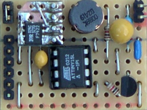
The device is available in both dual-inline (PDIP) and surface mount (SOIC) packaging. We used the PDIP package for breadboarding and the prototype circuit board, and have also built a surface-mount device (SMD) version:

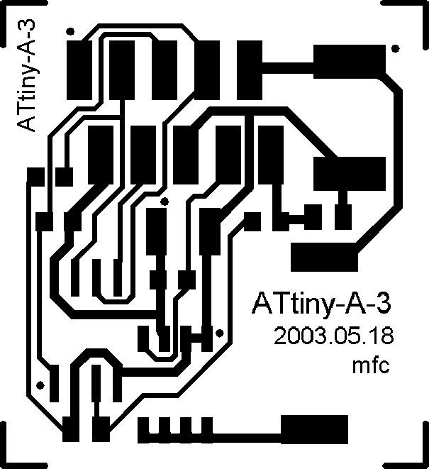
ATtiny SMD PCB
This board is 27mm × 25mm; here is the artwork (print at 600dpi). The circuit for the board is shown in this schematic.
The circuit is a buck topology switching regulator, with the current through the Luxeon LED sensed by measuring the voltage across a 0.22Ω resistor (R4). The microcontroller (IC2) varies its PWM output (on pin 6) and this drives the gate of the MOSFET in the Fetky device (Q1). The connection to the gate is taken off-board so it is automatically disconnected while the device is programmed.
The battery voltage is estimated using the voltage drop across an external diode (the debug LED mentioned below).
In the picture of the SMD board, above, the ATtiny15L is the square 8-pin device at the top left. Below the microcontroller is the Fetky device, and below the Fetky (at bottom left) is the inductor (L1).

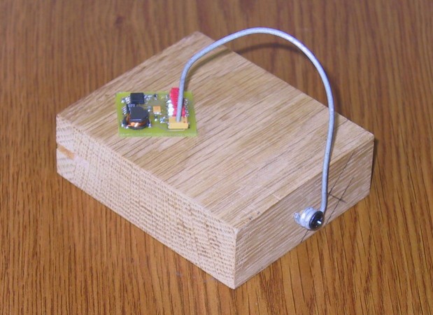
SMD component holder
Soldering even the small components is made easy using a simple SMD component holder (shown at right) or this simpler version. These are both made out of a wooden base and coat-hanger wire (or equivalent); the springiness of the wire holds the component to the board and to the base firmly, while allowing fine adjustment. The component can then be soldered at one point and any remaining connections can then be soldered with or without the aid of the holder. For more details, see this illustrated description.
Off-board circuitry
In use, eight connections from the board are used:
- Wires 2 & 6 connect to the battery pack. This must be 4×NiMh
or possibly 4×NiCad or 3×Alkaline; the microcontroller’s
maximum rated voltage is 6V, so 4×Alkaline cannot be used without
additional circuitry.
- Wires 3 & 4 connect to a pair of momentary change-over push-button
switches and a red/green LED indicator. The switches are used to
control the circuit:
SW0 short press Reduce power (1 of 5 levels) SW0 long press Turn off SW1 short press Increase power SW1 long press Turn on, or set power to full SW0 & SW1 short press Debug display SW0 & SW1 long press Debug display The red/green display LED is optional and is used for displaying the contents of registers, etc. (for example, to inspect the voltage across R4 or the PWM duty cycle). Similarly, one switch is optional – the light could easily be controlled using only one switch (SW1, which is connected to PB2 and which provides the INT0 interrupt for power-on).
Here’s how the switches and LEDs are connected in our prototype:
Vcc
|
Z
Z R 2k2 Current
Z limit ~1.5mA
|
+--+--+
| |
_|_ _|_ R/G LEDs in common
\G/= \R/= anode package
-+- -+- e.g., Tosiba
| | TLRAG297
o3 |
1 / |
PB0 --------o SW0 | Switches are
| momentary sealed
o2 | pushbutton,
| o3 e.g., APEM 18535
| 1 /
PB2 ----------|---o SW1
Vledr |
| o2
| |
| |
+--+--+
|
GND
PB2 is also ADC1, so we can use the constant forward drop across the Red diode at very low current to deduce Vbatt (=Vcc). As Vcc drops towards 4V, Vledr as a percentage of Vcc reduces (Vcc-Vledr is constant). The 330K resistor shown in the main schematic allows about 10uA through the LED, enough for a repeatable forward drop (and also a just-visible battery-connected indication). - Wires 7 & 8 are connected to each other, enabling the drive to
the Fetky.
- Wires 9 & 10 connect to the Luxeon LED.
Please note: if you build this circuit, you do so at your own risk. Modern batteries can deliver considerable power, and a short-circuit can cause a risk of fire. Components can fail, too, and battery chargers may not fully charge batteries, so, as always when caving, carry at least one spare light per person sufficient to get you out of the cave.
Petzl conversion
The board, switches, red/green LED, and a battery connector fit comfortably in the back of a small Petzl headlamp with its battery connectors removed (this picture shows an earlier version of the SMD board):

ATtiny Petzl conversion
The Luxeon LED fits in the front of the headlamp (with the existing bulb holder removed) and can be seen in this general view:

ATtiny Petzl view
In use, the switches control 5 power levels, each varying from the next by a factor of two. At full power, the Luxeon LED is driven at 350mA (the full current the LED is rated for), and the circuit draws about 250mA from the battery pack at nominal voltage (4.8V) at an efficiency of 92.5%. This should give seven or more hours of light if 2000mAh batteries are used.
At the second-to-lowest power (approximately 45mA) the light output is roughly equivalent to a typical ‘key chain’ LED light such as the Photon Micro-light ». (We tested this light in El Cuevón de la Pruneda in June 2002 and found it was quite possible to navigate and exit the cave with this level of light.)
The microcontroller also watches the battery voltage, and when this indicates that the battery pack is 75% discharged the output power is limited to 50%. This brightness is still very usable, and the limit increases the life of a battery pack.
Similarly, at further thresholds the light is switched to successively lower powers (at the lowest power the light should last for tens of hours). This reduction ensures that the caver is not suddenly left with no light at all, and the stepped nature of the reduction gives a noticeable warning.
The automatic power limits can be overridden for a 10 second “boost” at a higher power if required.
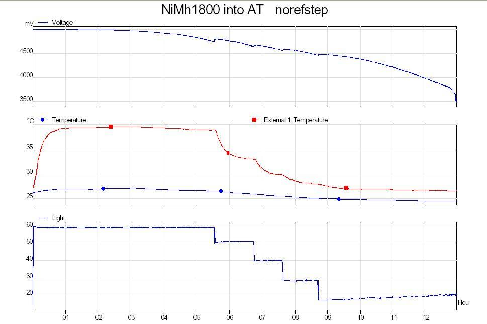
Graphs showing the discharge characteristics are available here. In this image, the three charts are (from top to bottom):
- Battery voltage. Note that the data logger hardware capped this
measurement at 5 volts, so the initial voltage appears flat when
it would have been a little above 5 volts.
- Star/O heatsink temperature (red) and the ambient temperature
close to the battery pack (blue).
- Light output (uncalibrated). This shows the automatic step-downs
taking place as the battery voltage drops below each threshold. Each
drop is accompanied by a slight battery recovery (seen in the top
graph) and a reduction in the heatsink temperature (middle graph).
The apparent slight increase in light output in the last few hours of the test is due to ambient light leakage (dawn occurring, in this case).
In summary, using 4×1800mAh AA batteries, the lamp operates at maximum output for about 5.5 hours, then at intermediate powers for a further 3 hours before being reduced to the lowest power.
Software
For contractual reasons we are unable to provide the software for this lamp at the moment (sorry! – but it might be possible to make it available later). If you would like to write your own, a good place to start is the Battery Charger Reference Design, available from the Atmel ATtiny 15L Product Card » (which also has links to the microcontroller datasheet, etc.). If this link does not work, please search the web for the Atmel AVR450 application note.